

Isolation Transformer for Telecommunication Equipment comes from what we see in telecom installations. Noise issues. Ground problems. Repeated failures.
Telecom equipment runs day and night. No breaks. No second chances. A small disturbance in power does not show up as smoke or sparks. It shows up as dropped signals. Data errors. Random shutdowns. And long troubleshooting hours where no one can point to a clear fault.
As a manufacturer of voltage stabilizers and isolation transformers, we have stood inside telecom rooms where everything looks fine, but nothing works smoothly. That is where power isolation starts to matter.
This article explains how a three phase isolation transformer fits into telecom systems. Not in theory. But in real installations.
Power issues we see in telecom installations
Telecommunication equipment is sensitive by nature. It listens more than it speaks. And noise travels faster than people expect.
We usually see four common problems.
First, electrical noise coming from the supply line. It rides along with power like dust in the air. You cannot see it. But sensitive circuits feel it.
Second, grounding issues. Different panels. Different earth points. One ground slightly higher than another. That difference creates ground loops. And ground loops create interference.
Third, DC leakage and harmonics. Modern telecom loads are non-linear. They pull current in bursts. Over time, this stresses components.
Fourth, shared power lines. Telecom equipment often shares supply with HVAC, elevators, or other heavy loads. Every start and stop sends disturbances downstream.
Many teams try to fix these problems with filters or better earthing alone. Sometimes it helps. Often it does not.
What a three phase isolation transformer actually does
A three phase isolation transformer separates the input supply from the load. Completely.
There is no direct electrical connection between the two sides. Power transfers magnetically. Like a message passed through a wall instead of an open door.
This separation blocks DC components. It reduces noise. And it breaks ground loops.
For telecom systems, this separation is not optional. It is protective.
If you want a basic explanation of isolation transformers, we have already covered that in our blog on what is a 3 phase isolation transformer. Here, we focus on how it behaves in telecom environments.
Isolation Transformer for Telecommunication Equipment – where it fits
In telecom rooms, the isolation transformer usually sits upstream of sensitive loads. Before rectifiers. Before UPS systems. Before control electronics.
Its job is simple. Keep the supply clean before it reaches equipment that cannot defend itself.
We often compare it to a noise-canceling wall. Not earphones. A wall. The noise stays outside. The signal stays inside.
When designed correctly, it does not affect normal operation. It only removes what should not be there.
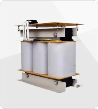
Inside the transformer: design choices that matter
At Rameshwar Power Control, we build isolation transformers with two isolated Faraday shields between primary and secondary windings.
Why two? Because one shield reduces noise. Two shields redirect it.
High-frequency noise gets diverted to ground before it reaches the load. And the primary and secondary grounds remain isolated from each other.
This design reduces:
- Coupling capacitance
- Leakage current
- Common mode noise
And in telecom systems, those three factors decide stability.
The core is designed so it does not saturate even when voltage rises. That matters during grid fluctuations. Especially in industrial areas.
Performance advantages that telecom systems benefit from
These are outcomes we see in the field.
- Very high noise attenuation capacity
- Reduced coupling capacitance
- Leakage current below 20 micro amps
- Suitable for higher harmonic loads
- Stable performance even at higher applied voltage
- Safe isolation during testing and servicing
- Scalable construction based on wound coils
Telecom teams usually notice the difference indirectly. Fewer alarms. Fewer unexplained resets. Cleaner signals.
Technical specifications used by telecom projects
We are listing these because telecom engineers ask for them. Not because spec tables look good.
- System connection: Delta / Star
- Input voltage: 415V, 3 phase
- Output voltage: 415V or 200V, 3 phase
- Ratio: 1:1 or 2:1
- Regulation: better than 3.5%
- Power factor: 0.75 lead or 0.75 lag
- Dielectric strength: 3 kV for 60 seconds
- Insulation resistance: above 1000 mega ohms
- Coupling capacitance: 0.1 pF for 80 dB
- Common mode attenuation: 80 dB / 100 dB
Construction follows IS 2026 Part I & II and IS 11171 standards.
Cooling, environment, and long-term reliability
Telecom rooms are not always ideal. Some are air-conditioned. Some are not.
Our isolation transformers are designed to operate between 0°C and 45°C.
Cooling options include:
- Natural air cooling
- Forced air cooling
- Oil-cooled execution for higher ratings
Closed-type construction protects against dust and accidental contact. This matters in shared equipment rooms.
Where telecom fits among other applications
While this article focuses on telecom, similar power issues exist in other sectors.
We supply isolation transformers for:
- Cell phone networks
- Large computer installations
- Analytical and scientific equipment
- Biomedical equipment
- CNC machines
- Printing and textile machinery
We have written separately about isolation transformers for CNC machines and scientific equipment. Telecom systems share the same sensitivity, just with different failure symptoms.
We see similar power sensitivity in CNC machines and scientific equipment. The failure patterns differ, but the root cause is the same. We have explained this in detail in our article on
Top 5 Benefits of Using an Isolation Transformer for CNC Machines
Selecting the right unit for telecom use
There is no universal size. Selection depends on:
- Load type and harmonic content
- Voltage level required downstream
- Noise attenuation needs
- Installation space and cooling
This is why we usually review drawings before suggesting a rating. Guesswork costs more later.
If voltage fluctuation is also present, teams often combine isolation transformers with servo voltage stabilizers. We have explained voltage drop behavior in detail in our blog on top voltage drop problems and solutions for industries.
Conclusion
An Isolation Transformer for Telecommunication Equipment is not about adding another box to the panel. It is about removing what does not belong in the power line.
From our experience as a manufacturer, telecom systems fail quietly when power quality is ignored. And they run quietly when isolation is done right.
If the system runs day and night, the power feeding it must be calm. That is what proper isolation provides.
If you need proper power control, contact us. Our team can help you choose the right solution.
